1. Prototype or validation status
These instructions use the current I/O board and enclosure design. See Project status for the latest hardware information.
2. Safety notice
- Disconnect USB power and leave the battery unplugged until all other connections are made and checked.
- Never short the battery leads. Make sure no screw or wire can pinch the battery cable.
- Check pin 1 at both ends of the 24-position cable before connecting it.
- Continuity-test each custom cable before connecting it to a board.
3. Required parts and tools
- Assembled I/O board, display board and printed case parts.
- 300 mm HY-to-HY, 4-pin latching I²C cable wired straight through.
- 150 mm PH2.0, 2-pin audio cable.
- Battery with a PH2.0, 2-pin connector. Important: Check the connector polarity against the markings on the Elecrow board.
- One 22 × 58 mm speaker and a PH2.0, 2-pin housing and contacts for the modified speaker lead.
- Sixteen M3 × 8 mm pan-head self-tapping screws.
- Seven M3 × 16 mm countersunk self-tapping screws.
- Screwdriver and the correct crimp tool for the cable contacts.
4. Procedure
Follow these steps after the I/O board, cables and enclosure parts are ready:
-
Install the battery with the cable facing the bottom-left corner. Secure it with the battery strap and two M3 × 8 mm screws. Take care not to damage the battery.
-
Lower the I/O board into the chassis, then push it forward so that the audio and key jacks clear the chassis wall. Secure the board with six M3 × 8 mm screws. The screw holes are marked with screw icons. Leave the three through-holes that will later secure the cover open.
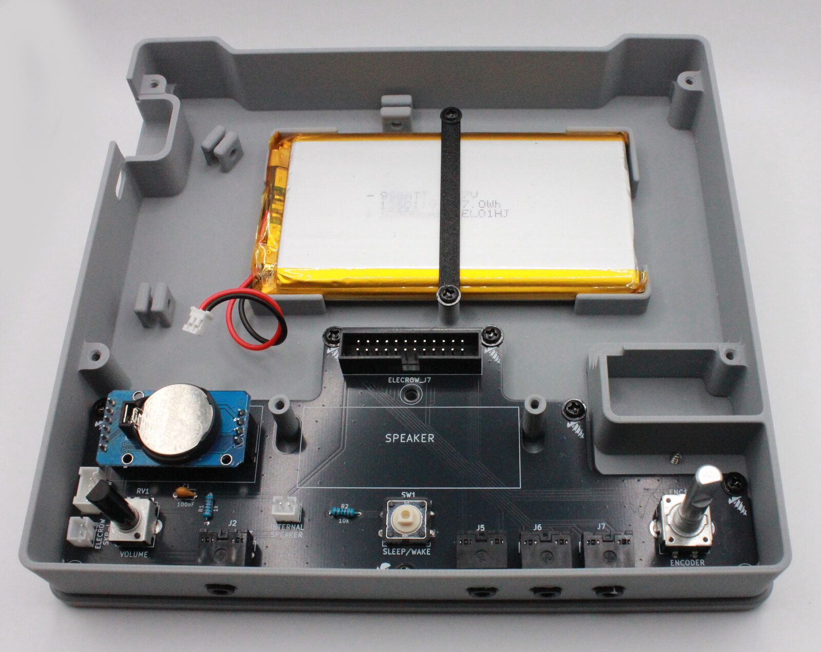
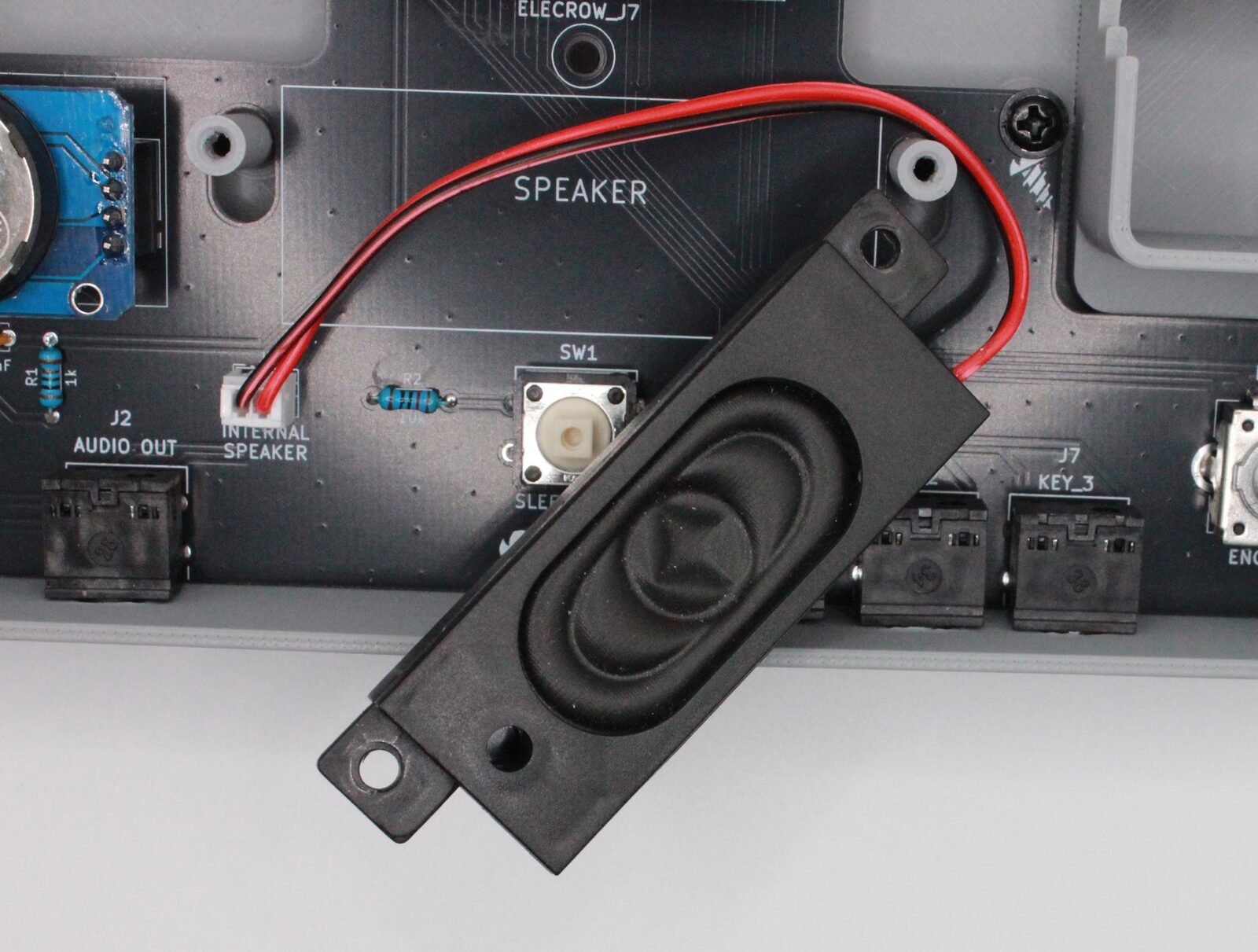
- Install the speaker. Route the cable around the right standoff and under the speaker. Keep the cable clear of the through-hole between J1 and the speaker, as well as the Sleep/Wake button. The 110 mm cable leaves just enough length for this route. Plug the speaker into J3, marked Internal Speaker.
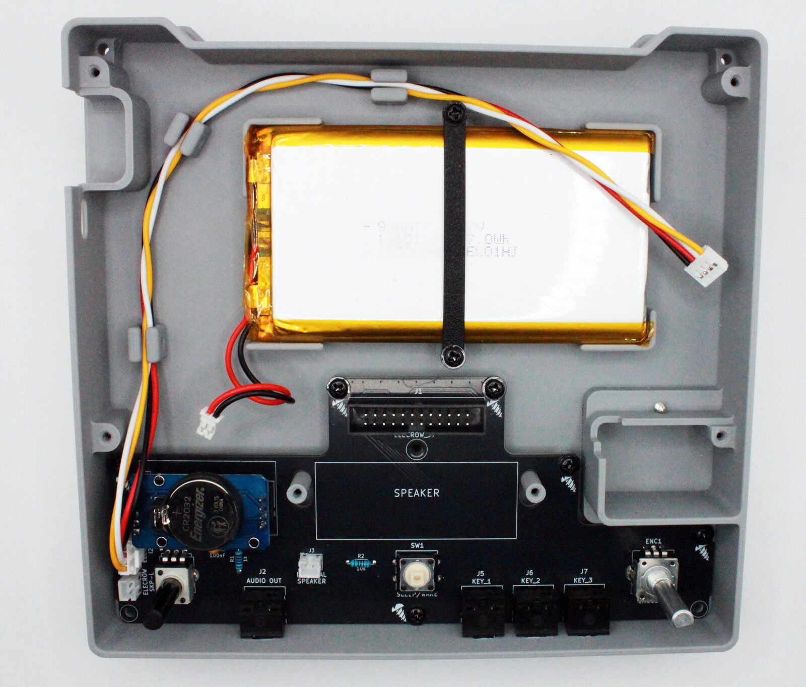
- Connect the latching HY I²C cable to J8, checking both pin 1 and the latch orientation. Use the cable-management features in the chassis to route the cable.
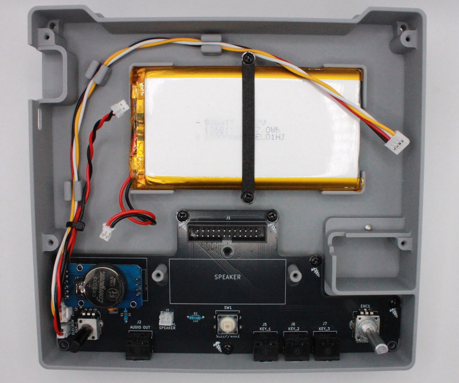
- Connect the PH2.0 audio cable. Use a cable tie to secure it to the I²C cable.
- Stand the Elecrow board on its edge and connect the audio and battery cables. Important: Pay close attention to the board markings. Both connectors are the same type, and connecting the battery to the audio output could damage the board.
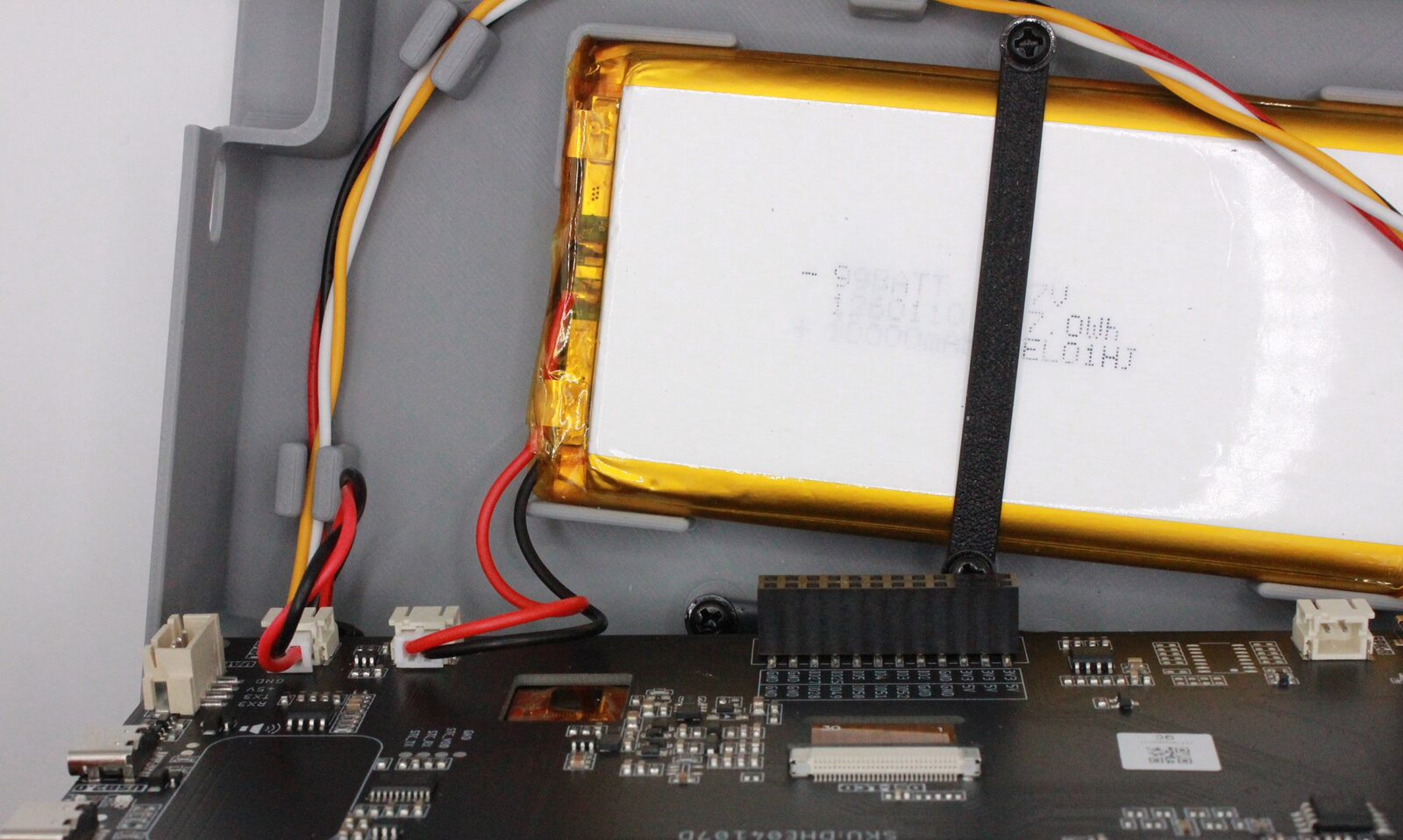
- Lean the Elecrow board toward the chassis and connect the I²C cable. Make sure that it is connected to the port labeled I²C1 on the board.
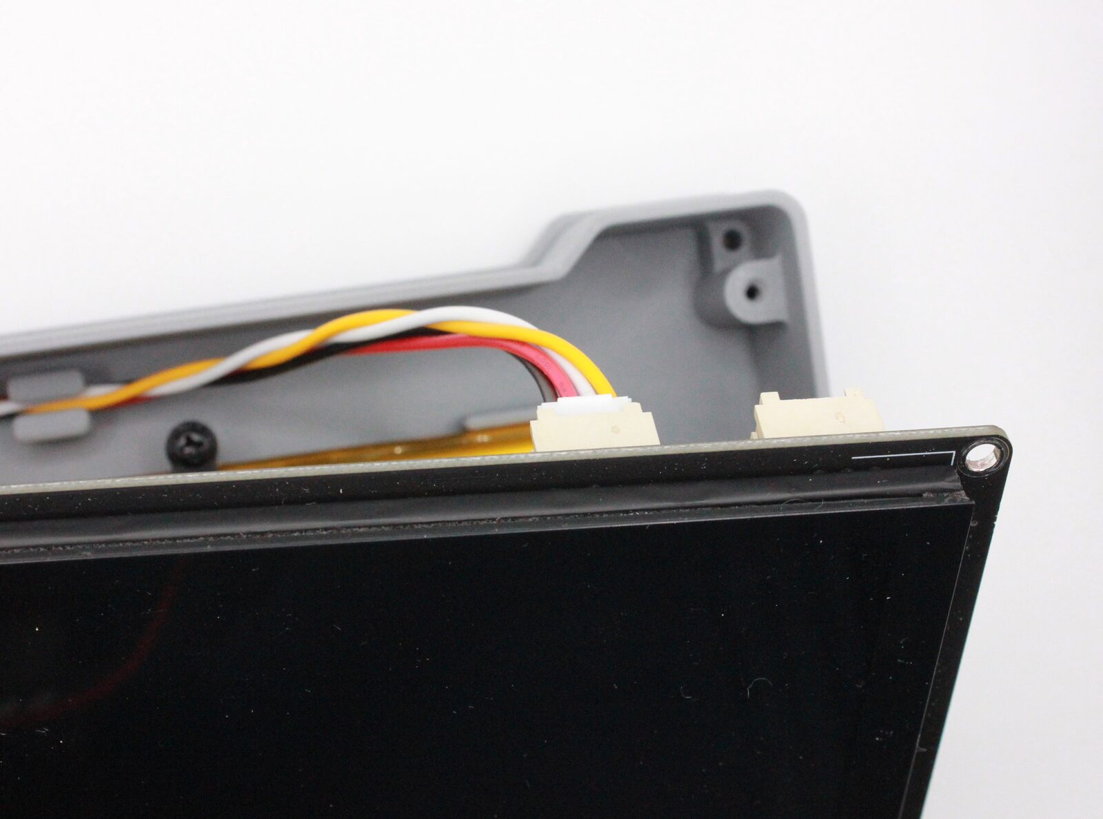
- Lower the Elecrow board onto the I/O board so that its 2 × 12 connector engages with the I/O board’s 2 × 12 socket. Do not press on the glass screen; push on the Elecrow PCB instead. Secure the board with four M3 × 8 mm screws. Tighten the screws carefully: clearance is minimal, and a metal screwdriver can damage the edge of the glass.
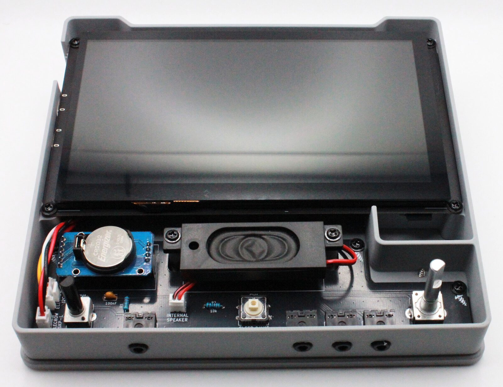
- Install the button and spring in the cover using two M3 × 8 mm screws. Attach the cover to the chassis with five M3 × 16 mm screws. Install the SD card access cover using two M3 × 16 mm screws, then install the knobs.
5. Expected result
A closed case with all controls and connectors accessible.
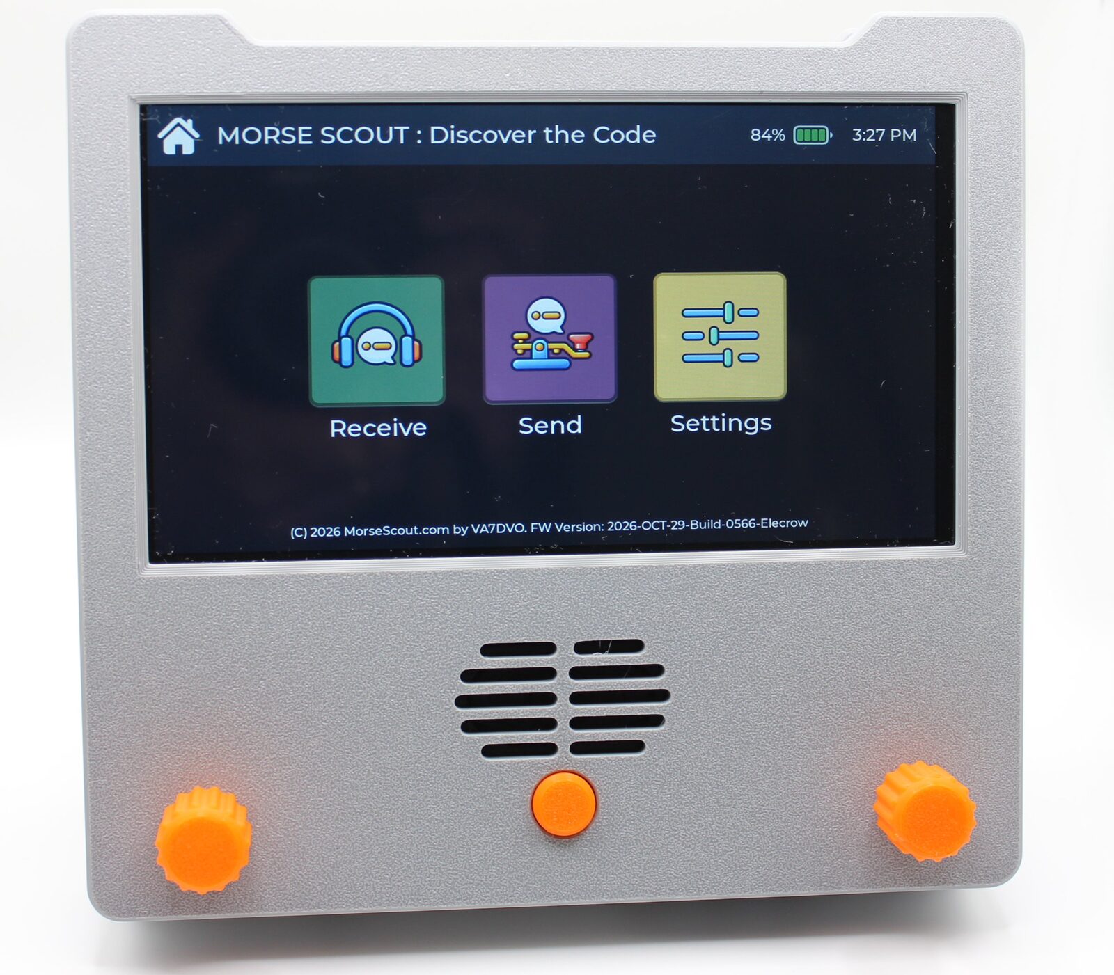
6. Inspection or test
The cover should sit flat, and the button should activate the Sleep/Wake switch.
7. Failure conditions
- The board does not power up: check the battery charge and polarity.
8. Next step
Wi-Fi coprocessor firmware, then First firmware installation.