1. Validation status
Validated for custom I/O PCB v1.2. A board fabricated from the v1.2 Gerbers passed these bring-up and functional checks. The page includes the current procedures and supporting screenshots.
2. Safety notice
If anything gets hot, smells, or the display board behaves erratically, disconnect USB power and the battery immediately and check the wiring.
3. Required parts and tools
- The assembled Morse Scout with firmware installed.
- A straight key and a paddle, or a single key you can test on each input.
- A FAT32 or exFAT microSD card with a
.txtfile on it. - A 2.4 GHz Wi-Fi network (optional).
4. Procedure
Start with Settings → Diagnostics. Use this screen to test the custom PCB and its connections before closing the case. Insert the microSD card before powering on. Have a stereo paddle or test plug available so you can exercise both tip and ring contacts on every key socket; a straight key alone may not test both contacts.
Run the diagnostic tests first
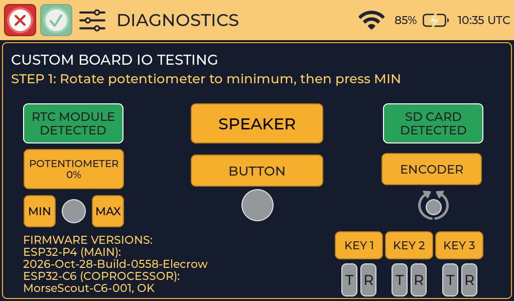
Start here and follow the on-screen instructions. RTC and SD-card indicators show detection status.
Follow the instruction line at the top of the screen:
- Turn the volume potentiometer to its minimum end stop and tap MIN.
- Turn it to its maximum end stop and tap MAX. Expect POTENTIOMETER PASSED. Rotate through the range and check that the displayed percentage changes smoothly. If the calibration range is too small, repeat both captures and check the wiring if the problem persists.
- Connect the paddle to Key 1. Press and release each contact separately. Both tip and ring indicators must pass and the key panel must show PASSED.
- Repeat both contacts at Key 2 and Key 3. Check every socket.
- Turn the rotary encoder in both directions, then press and release its push button. Expect both direction arrows to respond and ENCODER PASSED.
- Press and release the physical Sleep/Wake button. In Diagnostics, this tests the input while the device stays awake. Expect its panel to show PASSED.
Complete each press and release. A brief activity indication alone does not mean the test has passed; look for the completed green state and PASSED labels.
Check the modules and speaker
- RTC MODULE: Expect DETECTED and a green panel when the external RTC is connected. If it shows NOT DETECTED, check module power and I²C wiring. Detection does not verify clock accuracy or backup-battery retention.
- SD CARD: Expect DETECTED and a green panel when the card mounted successfully at startup. NOT DETECTED can mean no card or an unreadable filesystem. Power down before reseating the card, then restart. The indicator does not track insertion or removal while running.
- SPEAKER: After calibrating the knob, set a comfortable nonzero volume and tap SPEAKER once. Expect the complete five-note startup melody, clear and without crackle or distortion. Record whether you heard it; the firmware cannot confirm audible output.
Verify the Wi-Fi coprocessor firmware
Read the firmware panel near the bottom of Diagnostics. The ESP32-C6 line must show MorseScout-C6-001, OK. When the required firmware is verified, the UPDATE C6 FIRMWARE button is hidden.
If the C6 version is not recognized, unavailable, or requires an update, keep the device on this screen and open the Wi-Fi coprocessor firmware guide. Follow that guide before selecting UPDATE C6 FIRMWARE; it covers USB-power preparation, installation, verification, recovery, and retry steps.

Save the calibration

When the required control tests pass, the instruction line shows TEST PASSED and Accept becomes available. Tap Accept to save the potentiometer calibration. Cancel exits without saving the staged calibration.
Accept requires the potentiometer, six key contacts, encoder and Sleep/Wake tests. RTC, SD card and speaker results do not gate Accept. Record those results separately before declaring the assembly passed.
Complete the remaining checks
After leaving Diagnostics, work through these functional checks and record the results. In particular, verify normal sleep/wake behavior outside the diagnostic screen and open a file to confirm SD-card access.
| # | Check | How |
|---|---|---|
| 1 | Startup | The startup animation, melody and main menu appear. |
| 2 | Touch | Tap each main menu button. |
| 3 | Key inputs | In Settings → Keyer, set each input in turn and send in Send → Practice. |
| 4 | Paddle contacts | With a paddle, check dits and dahs are on the expected sides; adjust Contact Order if needed. |
| 5 | Rotary encoder | Turning clockwise moves the focus forward on a menu; a short press selects. |
| 6 | Volume knob | Turning clockwise raises the volume across the full range. Settings → Device → Volume follows the knob. |
| 7 | Speaker | Sidetone is clear, without crackle. |
| 8 | Sleep/wake | Press and release to sleep; press to wake. |
| 9 | microSD card | Open a .txt file in Receive → Book. For release filesystem verification, repeat with FAT32 and exFAT cards. |
| 10 | Speech | Receive → Words speaks the word with Say After on. |
| 11 | Wi-Fi | Settings → Wi-Fi finds and joins a network. |
| 12 | C6 firmware | Diagnostics shows MorseScout-C6-001, OK for the ESP32-C6 coprocessor. |
| 13 | Clock | With Wi-Fi connected and Automatic time, the clock appears. Turn off and on again: the time is still correct. |
| 14 | Battery | The battery percentage appears; the charging icon appears when charging. |
5. Expected result
Every check passes.
6. Inspection or test
Record the ESP32-P4 firmware version, the ESP32-C6 version and verification status, and the result of each check.
7. Failure conditions
See Build troubleshooting for each failed check.
8. Next step
Close the case and start practising with the User Manual.